2.3 Fading LED
As of now, we have only used two output signals: high level and low level (also called ON and OFF), which is called digital output. However, in actual use, many devices do not simply ON/OFF to work, for example, adjusting the speed of the motor, adjusting the brightness of the desk lamp, and so on. To achieve this goal, a slider that adjusts resistance was used in the past, but it is unreliable and inefficient. Therefore, Pulse width modulation (PWM) has emerged as a feasible solution to such complex problems.
A pulse is a digital output that contains a high level and a low level. The pulse width of these pins can be adjusted by changing the ON/OFF speed.
When we are in a short period of time (like 20ms, which is most people’s visual retention period), let the LED turn on, turn off, and turn on again, we won’t see it has been turned off, but the brightness of the light will be slightly weaker. During this period, the more time the LED is on, the brighter it becomes. In other words, in the cycle, the wider the pulse, the greater the “electric signal strength” output by the microcontroller. This is how PWM controls LED brightness (or motor speed).
There are some points to pay attention to when Pico uses PWM. Let’s take a look at this picture.
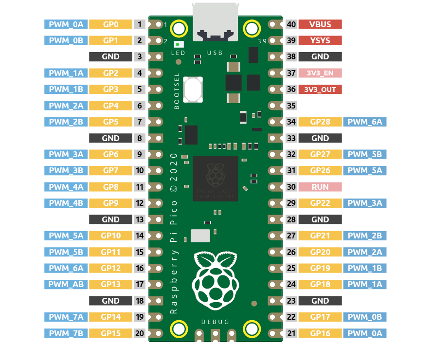
Pico supports PWM on each GPIO pin, but there are actually 16 independent PWM outputs (instead of 30), distributed between GP0 to GP15 on the left, and the right GPIO’s PWM output is identical to the left.
It is important to avoid setting the same PWM channel for different purposes during programming. For example, GP0 and GP16 are both PWM_0A.
Let’s try to achieve the faded LED effect after understanding this knowledge.
Schematic
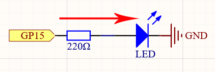
This project is the same circuit as the first project 2.1 Hello, LED!, but the signal type is different. The first project is to output digital high and low levels (0&1) directly from GP15 to make the LEDs light up or turn off, this project is to output PWM signal from GP15 to control the brightness of the LED.
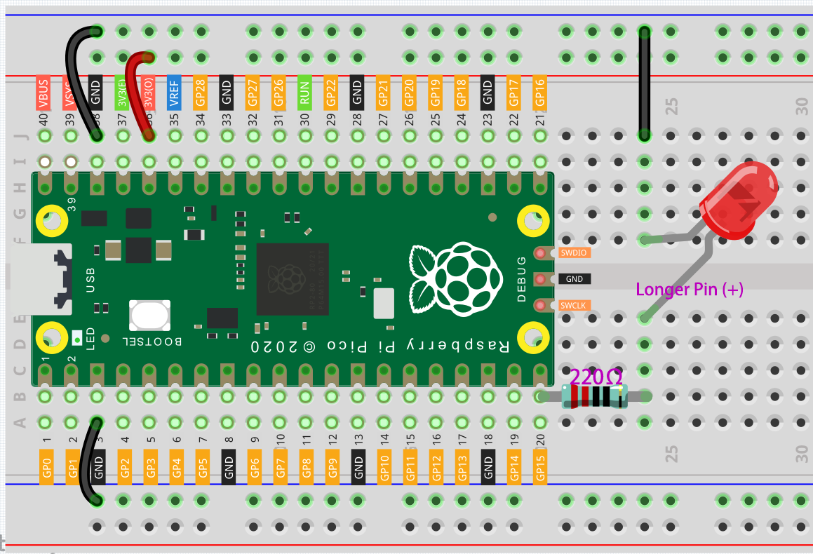
Wiring
Code
Note
Open the
2.3_fading_led.pyfile under the path ofeuler-kit/micropythonor copy this code into Thonny, then click “Run Current Script” or simply press F5 to run it.Don’t forget to click on the “MicroPython (Raspberry Pi Pico)” interpreter in the bottom right corner.
For detailed tutorials, please refer to Open and Run Code Directly.
import machine
import utime

led = machine.PWM(machine.Pin(15))
led.freq(1000)

for brightness in range(0,65535,50):
    led.duty_u16(brightness)
    utime.sleep_ms(10)
led.duty_u16(0)
The LED will gradually become brighter as the code runs.
How it works?
Here, we change the brightness of the LED by changing the duty cycle of the GP15’s PWM output. Let’s take a look at these lines.
import machine
import utime

led = machine.PWM(machine.Pin(15))
led.freq(1000)

for brightness in range(0,65535,50):
    led.duty_u16(brightness)
    utime.sleep_ms(10)
led.duty_u16(0)
led = machine.PWM(machine.Pin(15))sets the GP15 pin as PWM output.The line
led.freq(1000)is used to set the PWM frequency, here it is set to 1000Hz, which means 1ms (1/1000) is a cycle.The
led.duty_u16()line is used to set the duty cycle, which is a 16-bit interger(2^16=65536). A 0 indicates 0% duty cycle, which means each cycle has 0% time to output a high level, i.e., all pulses are turned off. The value 65535 indicates a duty cycle of 100%, which means the whole pulse is turned on, and the result is ‘1’. When it is 32768, it will turn on half a pulse, so the LED will be half as bright when fully on.