4.1 - Toggle the Joystick
If you play a lot of video games, then you should be very familiar with the Joystick. It is usually used to move the character around, rotate the screen, etc.
The principle behind Joystick’s ability to allow the computer to read our actions is very simple. It can be thought of as consisting of two potentiometers that are perpendicular to each other. These two potentiometers measure the analog value of the joystick vertically and horizontally, resulting in a value (x,y) in a planar right-angle coordinate system.
The joystick of this kit also has a digital input, which is activated when the joystick is pressed.
Schematic
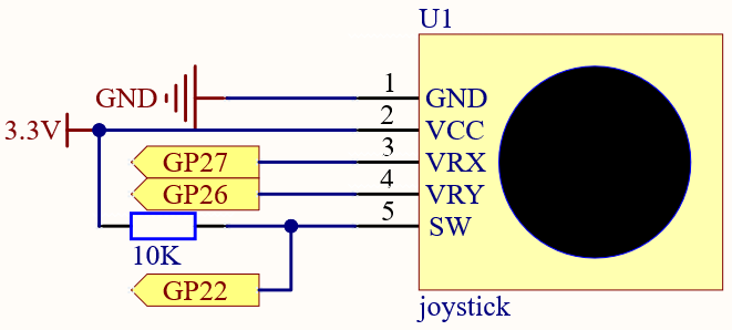
The SW pin is connected to a 10K pull-up resistor, the reason is to be able to get a stable high level on the SW pin (Z axis) when the joystick is not pressed; otherwise the SW is in a suspended state and the output value may vary between 0/1.
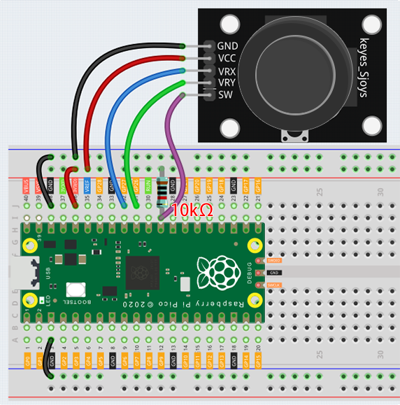
Wiring
Code
Note
You can open the file
4.1_toggle_the_joyostick.inounder the path ofeuler-kit/arduino/4.1_toggle_the_joyostick.Or copy this code into Arduino IDE.
For detailed tutorials, please refer to Open & Run Code Directly.
Or run this code directly in the Arduino Web Editor.
Don’t forget to select the Raspberry Pi Pico board and the correct port before clicking the Upload button.
After the program runs, the Shell prints out the x,y,z values of joystick.
The x-axis and y-axis values are analog values that vary from 0 to 65535.
The Z-axis is a digital value with a status of 1 or 0.