LED Matrix
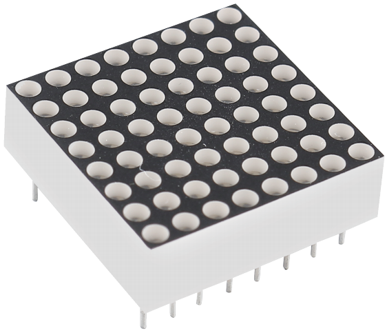
Generally, LED dot matrix can be categorized into two types: common cathode (CC) and common anode (CA). They look much alike, but internally the difference lies. You can tell by test. A CA one is used in this kit. You can see 788BS labeled at the side.
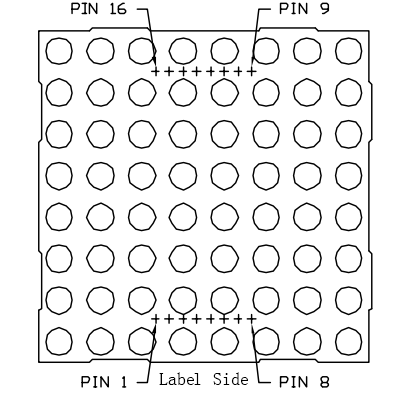
See the figure below. The pins are arranged at the two ends at the back. Take the label side for reference: pins on this end are pin 1-8, and oh the other are pin 9-16.
The external view:
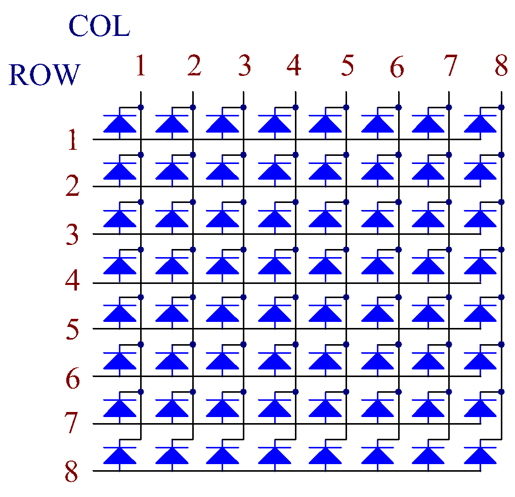
Below the figures show their internal structure. You can see in a CA LED dot matrix, ROW represents the anode of the LED, and COL is cathode; it’s contrary for a CC one. One thing in common: for both types, pin 13, 3, 4, 10, 6, 11, 15, and 16 are all COL, when pin 9, 14, 8, 12, 1, 7, 2, and 5 are all ROW. If you want to turn on the first LED at the top left corner, for a CA LED dot matrix, just set pin 9 as High and pin 13 as Low, and for a CC one, set pin 13 as High and pin 9 as Low. If you want to light up the whole first column, for CA, set pin 13 as Low and ROW 9, 14, 8, 12, 1, 7, 2, and 5 as High, when for CC, set pin 13 as High and ROW 9, 14, 8, 12, 1, 7, 2, and 5 as Low. Consider the following figures for better understanding.
The internal view:
Pin numbering corresponding to the above rows and columns:
COL |
1 |
2 |
3 |
4 |
5 |
6 |
7 |
8 |
Pin No. |
13 |
3 |
4 |
10 |
6 |
11 |
15 |
16 |
ROW |
1 |
2 |
3 |
4 |
5 |
6 |
7 |
8 |
Pin No. |
9 |
14 |
8 |
12 |
1 |
7 |
2 |
5 |
In addition, two 74HC595 chips are used here. One is to control the rows of the LED dot matrix while the other, the columns.
Example
5.4 8x8 Pixel Graphics (For MicroPython User)
7.12 Digital Bubble Level (For MicroPython User)
5.4 - 8x8 Pixel Graphics (For Arduino User)